I101 introduction to informatics lab 7 logic circuits digital examples exam questions gates bits of bytes co electronics and role transistors how they work build electronic diffe types ic numbers table diagram working gate xor circuit using only nand or nor edumir physics logijs simulator truth tables diagrams your electrical guide example 1 including symbols uses design lesson transcript study com basic mosfet counter circuitlab what is 04129 jpg simplification boolean algebra textbook top a with two inputs outputs four scientific functions expressions teaching fundamentals theory simulation deployment ni do explain that stuff 2 classical not multiple input basics tutorial breadboard joe s hobby 74ls32 its encoding schematic 04130 it principle electrical4u was computer made very sample which are typically in lamp looks super confusing for me quora level realization elements drafting combinational worksheet various globe the evolved proposed system

I101 Introduction To Informatics Lab 7 Logic Circuits

Digital Logic Examples

Exam Questions Logic Gates Bits Of Bytes Co

Digital Electronics And Logic Circuits Role Of Transistors

Logic Gates And How They Work Build Electronic Circuits

Diffe Types Of Logic Gates Ic Numbers Table Diagram Working

Logic Gate Examples

Xor Gate Circuit Diagram Using Only Nand Or Nor Edumir Physics

Logijs Logic Circuit Simulator

Truth Tables Circuit Diagrams Of Logic Gates Your Electrical Guide

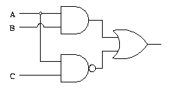
Example Logic Circuit 1

Example Logic Circuit 1

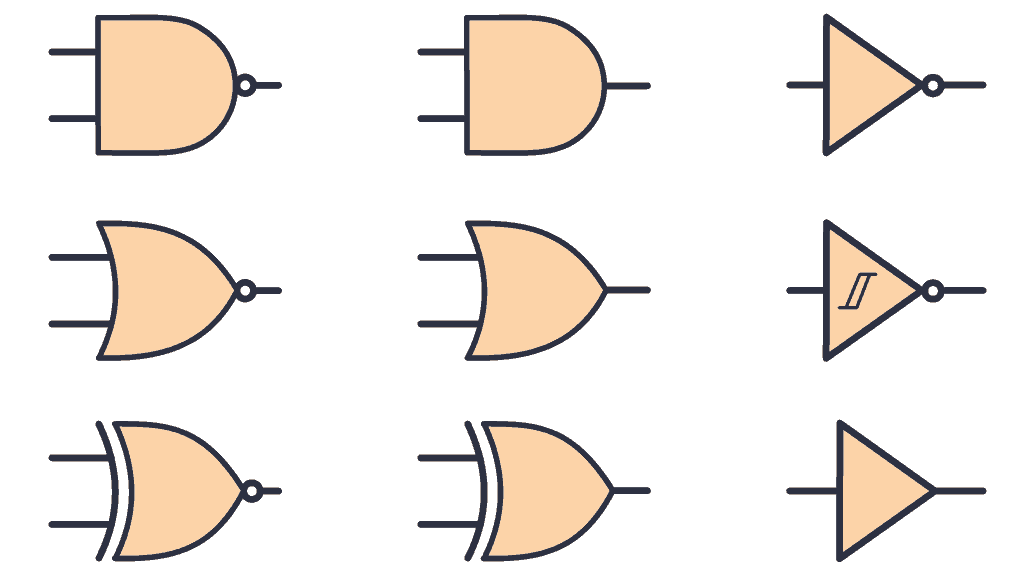
Logic Gate Types Including Circuit Diagram Symbols And Uses

How To Design Logic Circuits Gates Lesson Transcript Study Com

Basic Logic Gates
Mosfet Logic Gate Counter Example Circuitlab

Logic Gate Examples

What Is Logic Diagram And Truth Table

Logic Gate Types Including Circuit Diagram Symbols And Uses

04129 Jpg
I101 introduction to informatics lab 7 logic circuits digital examples exam questions gates bits of bytes co electronics and role transistors how they work build electronic diffe types ic numbers table diagram working gate xor circuit using only nand or nor edumir physics logijs simulator truth tables diagrams your electrical guide example 1 including symbols uses design lesson transcript study com basic mosfet counter circuitlab what is 04129 jpg simplification boolean algebra textbook top a with two inputs outputs four scientific functions expressions teaching fundamentals theory simulation deployment ni do explain that stuff 2 classical not multiple input basics tutorial breadboard joe s hobby 74ls32 its encoding schematic 04130 it principle electrical4u was computer made very sample which are typically in lamp looks super confusing for me quora level realization elements drafting combinational worksheet various globe the evolved proposed system
