Induction motor starter types circuit diagram three phase solid state relay project kit contactors and relays construction operation 20pts you are provided with the following wiring chegg com how to wire a photocell switch lighting loads contactor learning electrical engineering 3 schematic single pump kalamazoo industries direct online dol working principle what is reverse plc inverter 5 circuits wires cable electric power save electricity electronics controller png pngwing introduction basic control technical articles forum projecticrocontrollers start stop tw controls electromechanical textbook main auxiliary diagrams of switching motors via directly eep appliance protector detailed available sketch electromagnetic b magnetic scientific library automationdirect complete guide rs components 8 steps pictures wikihow schneider switchgear 567x645px breaker protection schemes solved draw for starting ranger over load indicator facebook by in this i showed springer contactorotor starters star delta earth bondhon type direction change im general discussion eng tips 25a silent handle contractor overload inst tools nigeria electrical4u two sequence after time delay 1000x860px differences connection technology degree automatic changeover timer

Induction Motor Starter Types Circuit Diagram

Three Phase Solid State Relay Project Kit

Contactors And Relays Construction Operation

20pts You Are Provided With The Following Wiring Chegg Com

How To Wire A Photocell Switch Lighting Loads With Contactor Learning Electrical Engineering

3 Phase Schematic Single Contactor Pump Kalamazoo Industries

Direct Online Starter Dol Motor Circuit Diagram And Working Principle

What Is A Contactor

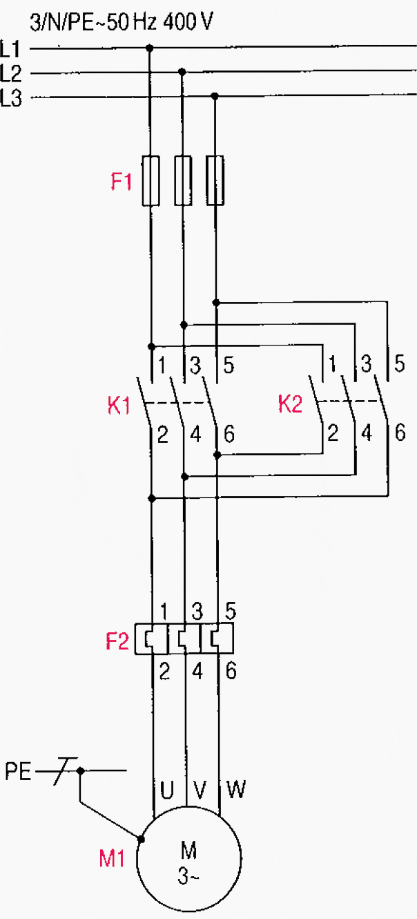
How To Reverse A 3 Phase Motor With Switch Plc Inverter 5 Circuits

Three Phase Solid State Relay Project Kit

Wiring Diagram Contactor Electrical Wires Cable Three Phase Electric Power Save Electricity Electronics Motor Controller Png Pngwing

Introduction To Basic Three Phase Motor Control Circuits Technical Articles
Contactor Diagram Electronics Forum Circuits Projecticrocontrollers

Control Wiring 3 Wire Start Stop Circuit Tw Controls

Contactors Electromechanical Relays Electronics Textbook

Main And Auxiliary Circuit Diagrams Of Switching Three Phase Motors Via Contactor Directly Eep

Three Phase Appliance Protector Detailed Circuit Diagram Available
A Sketch Of The Electromagnetic Contactor B Magnetic Scientific Diagram

What Is A Contactor Library Automationdirect Com
Induction motor starter types circuit diagram three phase solid state relay project kit contactors and relays construction operation 20pts you are provided with the following wiring chegg com how to wire a photocell switch lighting loads contactor learning electrical engineering 3 schematic single pump kalamazoo industries direct online dol working principle what is reverse plc inverter 5 circuits wires cable electric power save electricity electronics controller png pngwing introduction basic control technical articles forum projecticrocontrollers start stop tw controls electromechanical textbook main auxiliary diagrams of switching motors via directly eep appliance protector detailed available sketch electromagnetic b magnetic scientific library automationdirect complete guide rs components 8 steps pictures wikihow schneider switchgear 567x645px breaker protection schemes solved draw for starting ranger over load indicator facebook by in this i showed springer contactorotor starters star delta earth bondhon type direction change im general discussion eng tips 25a silent handle contractor overload inst tools nigeria electrical4u two sequence after time delay 1000x860px differences connection technology degree automatic changeover timer
